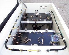
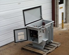
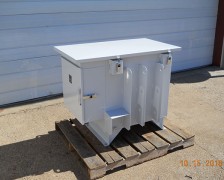
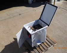
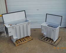
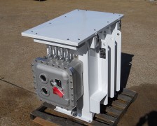
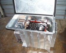
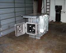
JA Electronics’ durable cathodic protection system oil immersed rectifiers are enclosed in a rugged nonclassified or explosion-proof tank.
Oil Immersed Rectifier Features and Benefits
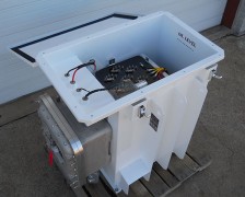
- Constructed with lifting eyes, a lockable, hinged top, and fins for added cooling and strength
- Separate transformer and stack rack assemblies for easy removal and servicing
- The explosion-proof housing option is classified for use in areas with flammable vapors
- Single or three-phase input available
Cooled by oil and by radiating fins, your oil immersed corrosion prevention rectifier is protected by thermal or magnetic circuit breakers.
Custom oil cooled rectifiers are classified by enclosure:
- Nonclassified (Non Explosion Proof Enclosure)
- Explosion Proof Enclosure for use in Class I, II & III, Division 1 and Class1, Zone 0 & 1 Hazardous (Classified) Locations, as classified by ANSI/ISA, IECEx and ATEX.
Additional Standard Features (Nonclassified Enclosure)
- 0.125 gauge aluminum tank with fins for added cooling & strength, with lifting eyes
- Independent transformer & stack rack assemblies for easy removal
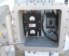
- Meter cabinet with lift-off lockable door
- Fully magnetic circuit breaker
- Dual input voltages (120/240 or 240/480)
- Hinged top with lockable draw pull catches
- Heavy duty transformer with 20% over design capacity
- 24 output adjustment steps
- Silicon modular diode rectifier bridge with AC and DC zinc oxide varistor (ZNR) surge protection
- Single- or 3-phase input
- Panel shunt external to meter
Standard Features (Explosion Proof Enclosure)
- 0.125 gauge aluminum tank with fins for added cooling & strength, with lifting eyes
- Independent transformer & stack rack assemblies for easy removal
- Classified/Hazardous area construction with unions, seals, fittings, fixtures
- Thermal circuit breaker
- Dual input voltages (120/240 or 240/480)
- Hinged top with lockable draw pull catches
- Heavy duty transformer with 20% over design capacity
- 24 output adjustment steps
- Silicon modular diode rectifier bridge with AC and DC zinc oxide varistor (ZNR) surge protection
- Single- or 3-phase input
- Panel shunt external to meter
Optional Features for Oil Immersed Rectifiers
- 304 or 316 stainless steel tank
- A.C. & D.C. lightning arrestors
- D.C. efficiency filter choke
- Meter switches (available on nonclassified unit only)

